Complete Installation Guide for Agricultural Junction Boxes
Step-by-step instructions for proper installation of waterproof junction boxes in farm environments, ensuring maximum protection and longevity.
Read Full Guide →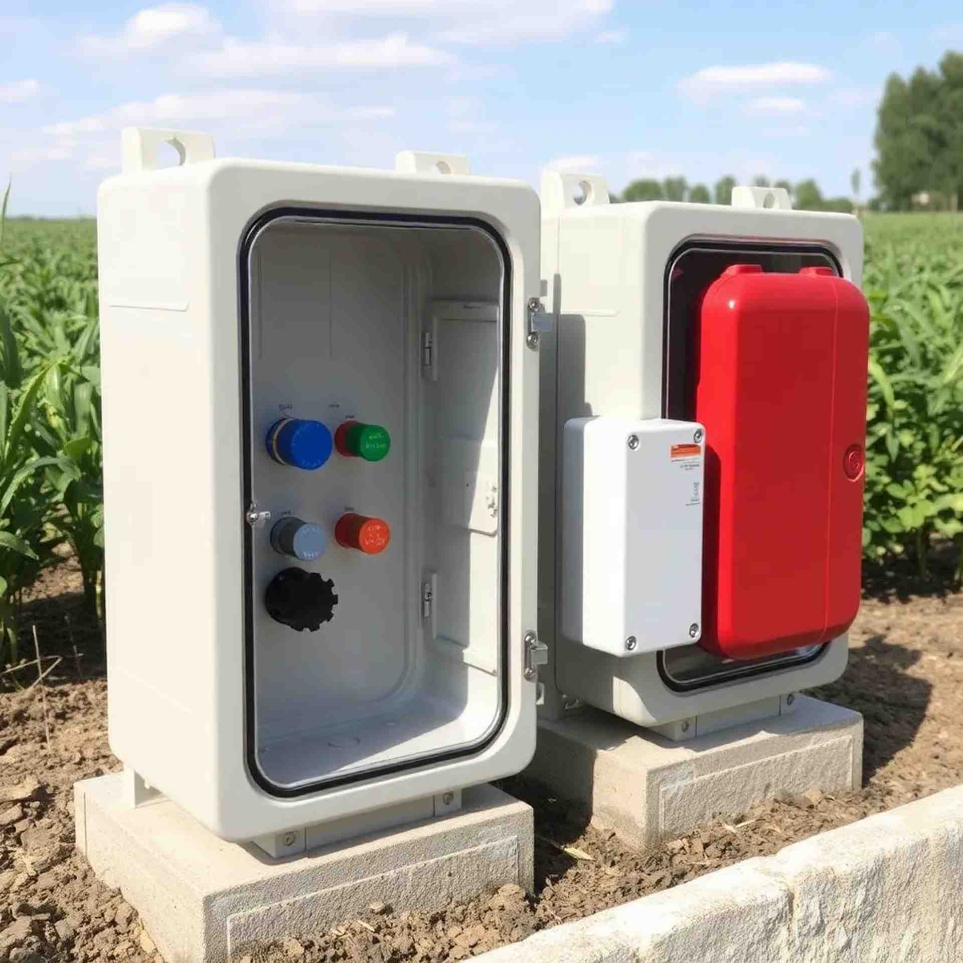
Understanding IP68 Rating: What It Means for Your Sensors
Learn about ingress protection ratings and why IP68 certification is essential for agricultural sensor protection in Malaysia's tropical climate.
Read Full Guide →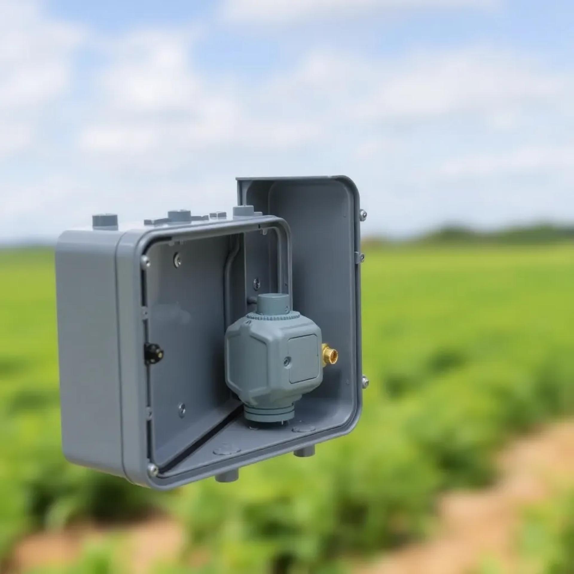
Cable Management Best Practices for Junction Boxes
Professional techniques for organizing cables inside junction boxes, preventing water ingress, and maintaining easy access for future maintenance.
Read Full Guide →
Preventive Maintenance Schedule for Junction Boxes
Recommended maintenance intervals and procedures to ensure your junction boxes continue providing reliable protection year after year.
Read Full Guide →
Common Issues and Solutions for Waterproof Enclosures
Identify and resolve the most common problems encountered with junction boxes in agricultural settings, from condensation to seal degradation.
Read Full Guide →
Integrating Multiple Sensors in a Single Junction Box
Guidelines for safely connecting multiple agricultural sensors within one enclosure, including wiring diagrams and terminal block configurations.
Read Full Guide →Complete Installation Guide for Agricultural Junction Boxes
Published: January 15, 2025 | Reading Time: 8 minutes
Pre-Installation Checklist
Before beginning installation, ensure you have the following:
- AquaShield junction box appropriate for your application
- Cable glands matching your cable diameters
- Mounting hardware (included with most models)
- Appropriate tools: screwdrivers, spanners, cable strippers
- Silicone sealant (marine-grade recommended)
- Cable ties and labels for organization
Step 1: Location Selection
Choose a mounting location that:
- Is easily accessible for future maintenance
- Provides adequate clearance for cable routing
- Minimizes exposure to direct mechanical impact
- Allows proper drainage (avoid mounting in depressions)
- Is close to sensor locations to minimize cable runs
Step 2: Mounting the Junction Box
For wall or post mounting:
- Mark mounting hole positions using the box as a template
- Drill pilot holes appropriate for your mounting surface
- Use stainless steel screws and washers to prevent corrosion
- Ensure the box is level and securely fastened
- Leave a slight gap at the bottom for potential drainage
Step 3: Cable Entry Preparation
Proper cable gland installation is critical for maintaining IP68 rating:
- Select the appropriate knockout or pre-drilled entry point
- Install cable glands hand-tight, then use a spanner for final tightening
- Ensure rubber seals are properly seated
- Use blanking plugs for unused cable entries
- Apply thread sealant to gland threads for extra protection
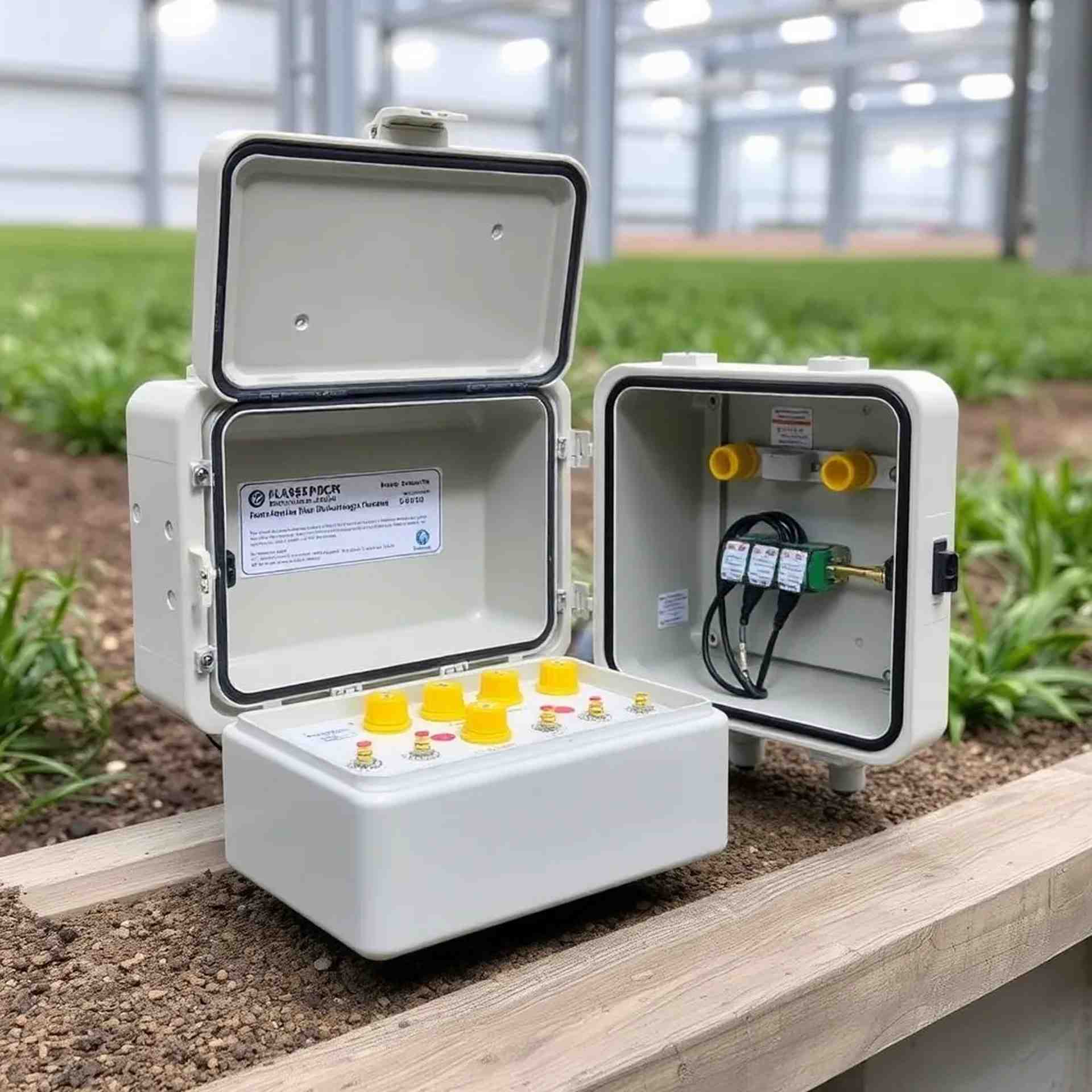
Step 4: Internal Wiring
Best practices for wiring inside the junction box:
- Strip cable outer sheathing only inside the box
- Use terminal blocks for all connections
- Label all cables clearly at entry and terminal points
- Maintain color coding throughout (red=positive, black=negative, etc.)
- Secure cables with tie-down points inside the box
- Keep adequate service loop for future modifications
Step 5: Final Checks and Sealing
Before closing the junction box:
- Verify all connections are secure and properly terminated
- Check that no bare wires are exposed
- Inspect the gasket seal for any damage or debris
- Clean the mating surfaces of lid and body
- Close lid evenly, tightening screws in a cross pattern
- Perform continuity tests on all circuits
Post-Installation Testing
After installation, verify:
- All sensors are reading correctly
- No moisture visible inside the enclosure
- Cable glands are tight and not leaking
- Mounting is secure and stable
- Documentation is complete (installation date, configuration, etc.)
Understanding IP68 Rating: What It Means for Your Sensors
Published: January 10, 2025 | Reading Time: 6 minutes
What is IP Rating?
IP (Ingress Protection) rating is an international standard (IEC 60529) that defines the level of protection provided by an enclosure against intrusion of solid objects and liquids.
Breaking Down IP68
The IP code consists of two digits:
- First Digit (6): Protection against solid objects
- 6 = Dust-tight: No ingress of dust whatsoever
- Complete protection against contact
- Highest level of solid particle protection
- Second Digit (8): Protection against liquids
- 8 = Protected against continuous immersion in water
- Suitable for prolonged submersion under specified conditions
- Typically tested at depths of 1-3 meters for 30 minutes or more
Why IP68 Matters in Malaysian Agriculture
Malaysia's tropical climate presents unique challenges:
- Heavy Rainfall: Monsoon seasons bring intense, prolonged rain that can overwhelm lesser-rated enclosures
- High Humidity: Constant moisture in the air can lead to condensation inside poorly sealed boxes
- Flooding: Low-lying agricultural areas may experience temporary submersion during heavy rains
- Dust and Debris: Agricultural environments generate significant dust, especially during dry seasons
IP68 vs Other Common Ratings
- IP65: Protected against water jets but not submersion - insufficient for many farm applications
- IP66: Protected against powerful water jets - better but still vulnerable to flooding
- IP67: Protected against temporary immersion (up to 1m for 30 min) - adequate for most applications
- IP68: Protected against continuous immersion - best choice for critical sensor protection
Maintaining IP68 Protection
To ensure your junction box maintains its IP68 rating:
- Regularly inspect gasket seals for wear or damage
- Ensure all cable glands are properly tightened
- Replace gaskets every 2-3 years or when damaged
- Clean mating surfaces before closing the enclosure
- Use only manufacturer-approved replacement parts
Cable Management Best Practices for Junction Boxes
Published: December 28, 2024 | Reading Time: 7 minutes
The Importance of Proper Cable Management
Poor cable management can lead to:
- Water ingress through improperly sealed cable entries
- Damaged wires from excessive bending or strain
- Difficult troubleshooting and maintenance
- Accidental disconnections during service
- Reduced lifespan of both cables and junction box
Cable Entry Best Practices
- Choose the Right Cable Gland Size:
- Measure your cable's outer diameter accurately
- Select a gland that provides a snug fit
- Avoid oversized glands that compromise sealing
- Proper Gland Installation:
- Hand-tighten first to ensure proper thread engagement
- Use a spanner for final tightening (don't over-tighten)
- Verify the compression seal is properly engaged
- Check that the cable cannot be pulled through
- Cable Routing Outside the Box:
- Provide a drip loop below the cable entry point
- Secure cables to prevent wind damage
- Use UV-resistant cable ties
- Avoid sharp bends near the gland
Internal Cable Organization
Inside the junction box:
- Strip outer sheathing only as far as necessary
- Route cables along the perimeter when possible
- Use cable ties at mounting points inside the box
- Maintain adequate service loop (5-10cm extra length)
- Keep power and signal cables separated where applicable
- Label both ends of every cable
Terminal Block Connections
For reliable terminal connections:
- Strip wire insulation to the exact length needed (typically 8-10mm)
- Ensure no stray strands that could cause shorts
- Use ferrules on stranded wire for better connection
- Tighten terminal screws firmly but don't over-torque
- Verify each connection with a gentle pull test
- Use jumpers for common connections rather than doubling up wires
Color Coding and Labeling
Implement a consistent labeling system:
- Use standard color codes: Red (positive), Black (negative), Green/Yellow (ground)
- Label cables at entry point and terminal end
- Include sensor ID or location in label
- Use waterproof labels or label makers
- Create a wiring diagram and keep it with installation documentation
Preventive Maintenance Schedule for Junction Boxes
Published: December 20, 2024 | Reading Time: 5 minutes
Why Regular Maintenance Matters
Regular preventive maintenance ensures:
- Continued IP68 protection effectiveness
- Early detection of potential failures
- Extended lifespan of equipment
- Reduced downtime and repair costs
- Reliable sensor data collection
Monthly Inspection (5-10 minutes)
Perform these quick checks monthly:
- Visual inspection of junction box exterior for cracks or damage
- Check that all cable glands are tight
- Verify mounting hardware is secure
- Look for signs of water ingress (moisture on exterior)
- Ensure no vegetation is blocking or touching the box
Quarterly Maintenance (20-30 minutes)
Every three months, perform a more thorough inspection:
- Open the junction box and inspect for internal moisture
- Check gasket seal condition - look for compression set or cracks
- Verify all terminal connections are tight
- Inspect cables for signs of damage or rodent activity
- Clean interior of any dust or debris
- Test sensor readings to ensure proper operation
- Document findings and any corrective actions taken
Annual Service (1-2 hours)
Once per year, conduct comprehensive maintenance:
- Complete Disassembly:
- Remove all cable connections
- Take photos before disconnecting for reference
- Label everything clearly
- Thorough Cleaning:
- Clean all interior surfaces
- Remove any corrosion with appropriate cleaner
- Dry completely before reassembly
- Component Replacement:
- Replace gasket seal (recommended every 2-3 years)
- Replace any damaged cable glands
- Check and replace mounting hardware if corroded
- Testing:
- Perform continuity tests on all circuits
- Verify sensor calibration
- Check system integration and data logging
Maintenance Record Keeping
Maintain detailed records including:
- Date of each inspection
- Findings and observations
- Parts replaced
- Issues identified and corrective actions
- Next scheduled maintenance date
Common Issues and Solutions for Waterproof Enclosures
Published: December 15, 2024 | Reading Time: 7 minutes
Issue 1: Condensation Inside the Box
Symptoms: Water droplets or moisture visible inside an otherwise sealed enclosure.
Causes:
- Temperature fluctuations causing trapped air to condense
- Breathing effect as box heats and cools
- Moisture trapped during installation
Solutions:
- Install a breather membrane (maintains IP68 while allowing pressure equalization)
- Use desiccant packets inside the enclosure
- Ensure box is completely dry before sealing
- Install during low-humidity periods when possible
Issue 2: Water Ingress Through Cable Glands
Symptoms: Water visible inside box, particularly near cable entries.
Causes:
- Improperly sized cable glands
- Insufficient tightening
- Damaged or worn seals
- Cable outer sheath removed too far back
Solutions:
- Verify correct gland size for cable diameter
- Retighten all cable glands properly
- Replace damaged glands and seals
- Apply thread sealant to gland threads
- Ensure drip loops are properly formed
Issue 3: Gasket Seal Failure
Symptoms: Water leaking around lid perimeter, visible gaps in seal.
Causes:
- Aged or UV-damaged gasket
- Compression set from prolonged closure
- Debris on sealing surfaces
- Uneven lid tightening
Solutions:
- Replace gasket (recommended every 2-3 years)
- Clean both mating surfaces thoroughly
- Tighten lid screws in cross pattern for even pressure
- Inspect gasket before every closure
Issue 4: Corrosion of Internal Components
Symptoms: Green or white deposits on terminals, difficulty making connections.
Causes:
- Moisture ingress
- Dissimilar metals in contact
- Salt air in coastal areas
Solutions:
- Address any moisture ingress issues first
- Clean corroded terminals with appropriate cleaner
- Apply dielectric grease to connections
- Use stainless steel hardware throughout
- Consider conformal coating for extreme environments
Issue 5: Mechanical Damage
Symptoms: Cracks, dents, or broken mounting points on enclosure.
Causes:
- Impact from equipment or tools
- UV degradation of plastic materials
- Over-tightening of screws
Solutions:
- Replace damaged enclosures - repairs rarely restore full IP rating
- Relocate box to more protected location if repeatedly damaged
- Use protective guards or barriers if necessary
- Choose metal enclosures for high-impact areas
Integrating Multiple Sensors in a Single Junction Box
Published: December 8, 2024 | Reading Time: 6 minutes
Benefits of Multi-Sensor Integration
- Reduced number of enclosures to maintain
- Centralized wiring for easier troubleshooting
- Cost savings on enclosures and installation
- Simplified system architecture
Planning Your Multi-Sensor Setup
Before integrating multiple sensors:
- Assess Sensor Compatibility:
- Check voltage requirements (all sensors should use same supply voltage)
- Verify current draw doesn't exceed supply capacity
- Consider signal types (analog vs digital)
- Choose Appropriate Box Size:
- Allow adequate space for terminal blocks
- Ensure sufficient cable entry points
- Leave room for service loops and future additions
- Plan Cable Routing:
- Group sensors by location to minimize cable runs
- Consider future expansion needs
- Plan for both power and signal cables
Wiring Configuration Options
Star Configuration:
- Each sensor has its own dedicated cable to the junction box
- Best for: Critical sensors, mixed sensor types
- Advantages: Easy troubleshooting, isolated failures
- Disadvantages: More cables to manage
Daisy-Chain Configuration:
- Power and ground distributed through multiple sensors
- Best for: Sensors in a line, standardized installations
- Advantages: Fewer cables, simpler routing
- Disadvantages: Failure can affect multiple sensors
Terminal Block Organization
Organize your terminal blocks systematically:
- Power Distribution Section:
- Positive supply rail
- Negative/ground rail
- Use jumpers to distribute power
- Signal Connections Section:
- Group by sensor or by signal type
- Label clearly
- Leave spare positions for future sensors
- Output Section:
- Connections to data logger or controller
- Clearly marked with destination
Common Wiring Mistakes to Avoid
- Mixing different voltage levels without proper isolation
- Overloading power supply capacity
- Poor labeling leading to confusion during maintenance
- Inadequate service loops making future changes difficult
- Crossing power and signal cables unnecessarily
Testing Multi-Sensor Installations
Verify proper operation:
- Test each sensor individually before connecting to system
- Verify correct voltage at each sensor connection
- Check for ground loops or interference
- Confirm all sensors are reporting to data logger
- Document baseline readings for future reference